Insulated-gate bipolar transistors (IGBTs) are at the heart of modern high-power electronic systems, such as welding machines and industrial motor drives. Managing their heat dissipation effectively is crucial for maintaining performance, reliability, and component lifespan. This blog shows how CFD analysis can be applied to analyze and optimize the cooling performance of IGBT modules. The study highlights how CFD simulation enables detailed thermal insights and design optimization of an IGBT module, cooled by a liquid-cooled cold plate. Different Thermal interface materials are also compared.
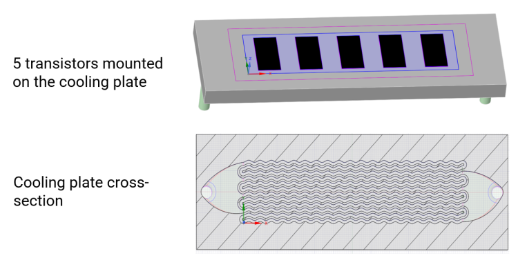
A five-transistor IGBT module without a backplate was selected for the combined thermal and CFD analysis. The total heat power was 4.8 kW, distributed across the module and dissipated through a cold plate cooled with a 50% ethylene glycol–water mixture at 40°C. All different layers between the transistors and cold plates were modeled separately but the structure of the transistors was simplified:
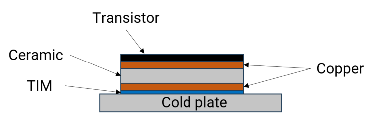
Each copper or ceramic layer was approximately 300 μm thick. The cold plate featured four flow channels with three bypasses to ensure even flow distribution. The inlet flow rate was 9.6 L/min, which allowed efficient heat removal while maintaining acceptable pressure losses.
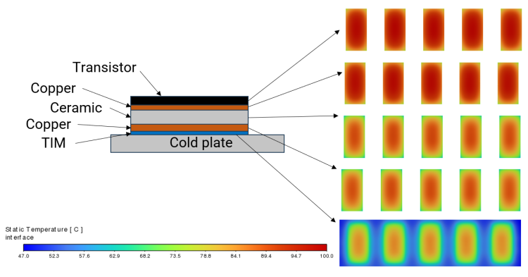
The average transistor temperature reached approximately 92°C under full load. Although the insulating and spreading layers were thin, the results confirmed that every layer plays a meaningful role in the module’s thermal resistance:
The figure below shows the temperature distribution in each layer.
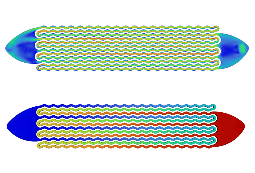
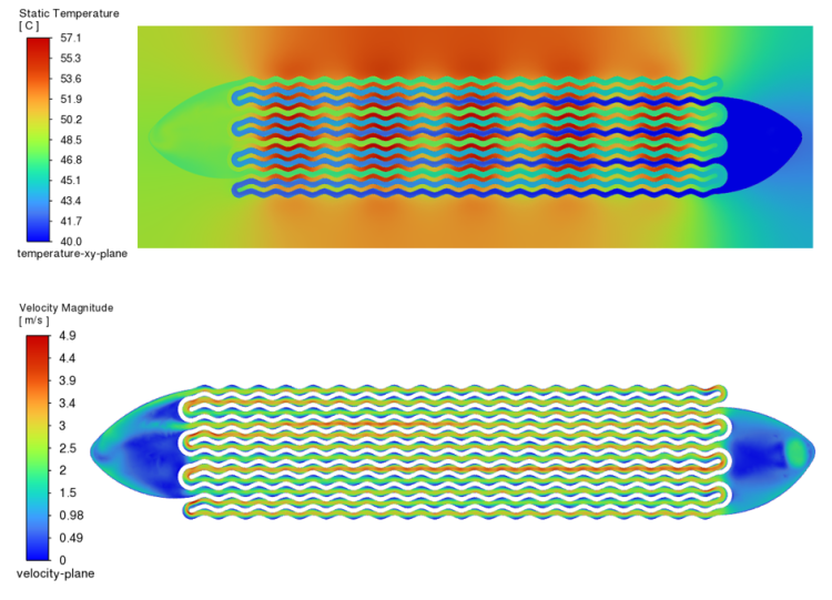
The simulation revealed that the temperature difference between transistors was less than 1°C, indicating uniform cooling performance. Cold plate design can mitigate temperature difference of incoming and outcoming fluid. Uniform temperate distribution in the fluid also decreases pressure loss because the viscosities of glycol mixtures are temperature sensitive. The figure below shows the temperature and velocity magnitude distributions in the cold plate.
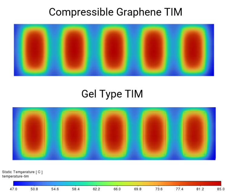
The CFD simulation compared two TIM materials. A compressible graphene-based TIM was used as the reference case and compared against an alternative gel-type TIM. The results showed that replacing the graphene TIM with a gel-based one increased the average transistor temperature from about 92°C to 107°C, demonstrating that TIM selection has a significant impact under high heat flux conditions. In high-current IGBT modules, the choice of TIM plays a significant role in determining the cooling efficiency.
Uutiskirjeessä avaamme laskentamaailman saloja helposti ymmärrettävässä muodossa. Tavoitteemme on tuottaa hyödyllisiä tietoiskuja sekä lujuus- että virtauslaskennasta. Uutiskirje julkaistaan noin 2–3 kk välein ja se ovat mahdollista perua milloin tahansa.